Dakota CMX10-DL Full Wave Capture Thickness Gauge
Advanced Ultrasonic Thickness Gauge for Corrosion Inspection & Precision Measurement
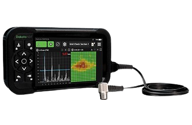
Dakota CMX10-DL is an advanced ultrasonic thickness gauge designed for corrosion inspection, precision thickness measurement, A-Scan & B-Scan analysis, and full wave capture applications. Built with rugged IP65 protection and advanced waveform analysis technology, the CMX10-DL provides accurate and reliable inspection results in demanding industrial environments.
Key Features of CMX10-DL
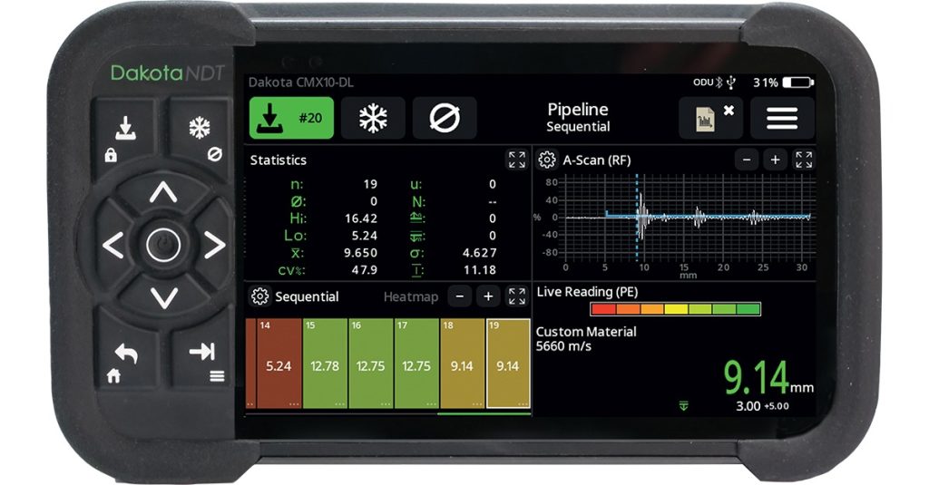
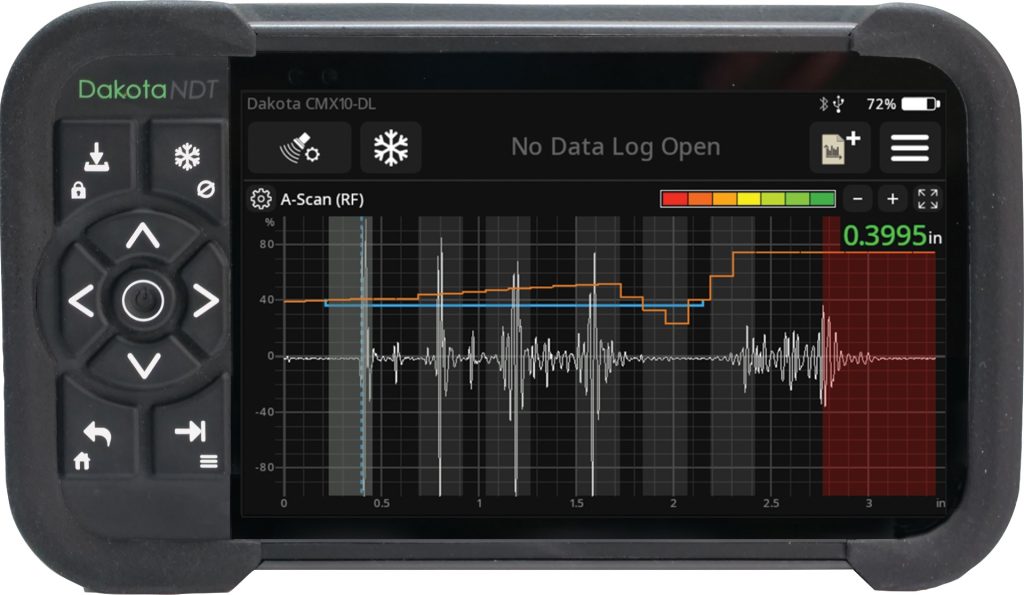
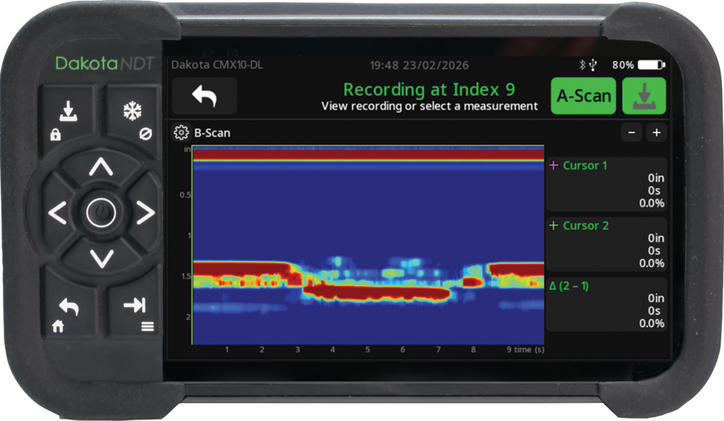
- Full Wave Capture with A-Scan & B-Scan Display
- Time Corrected Gain (TCG) & Backwall Echo Attenuation (BEA)
- Corrosion & Precision Thickness Measurement
- Second Layer / Cladding Inspection Capability
- Crack Prove-Up Capability
- High Resolution Waveform Analysis
- Data Logging & Full Traceability
- Touchscreen + Keypad Dual Operation
- USB & Bluetooth® LE Data Output
- Compatible with DakMaster™ Reporting Software
- Rugged IP65 Dust & Water Resistant Design
- Up to 15 Hours Battery Life
Dakota CMX10-DL Features Explained
Time Corrected Gain (TCG) Improve possibility of detection
Time Corrected Gain (TCG) and filtering lets you lift later echoes without saturating the near surface. That is useful on rough or heavily corroded backwalls where the important echoes are weak and buried in noise.
Backwall Echo Attenuation (BEA) – enables on screen monitoring of backwall signal amplitude. A drop in backwall amplitude indicates an issue, useful in composite inspections and many other materials.
Second Layer Inspection Less intrusive inspection better remaining life assessment
The second layer/cladding measurement feature is about seeing the true condition of the base metal and liner separately.
The gauge interprets multiple echoes so it can distinguish the outer wall from the inner liner or cladding layer beneath. In practice, that means you can get one reading for total wall and another that represents the remaining thickness of the inner liner, or outer liner, even when it is behind a coating or outer shell.
Crack Prove-Up Capability Fast confirmation of critical flaw
High-resolution, accurate crack prove-up capability for fast confirmation of critical flaws, even in complex geometries.
The Dakota CMX10-DL Thickness Gauge increases the probability of detection of hard to detect pits and cracks using traditional angle transducer inspection methods, to supporting confident fitness-for-service decisions.
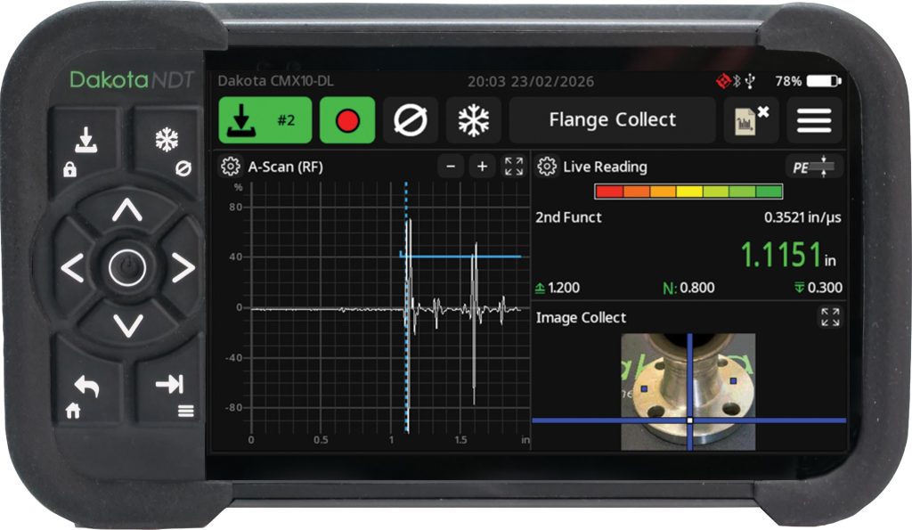
Image Collect For guided inspection locations
Upload a custom photo or CAD model of the part via DakMaster™ and then tap on that image to drive the next measurement location directly on the gauge itself.
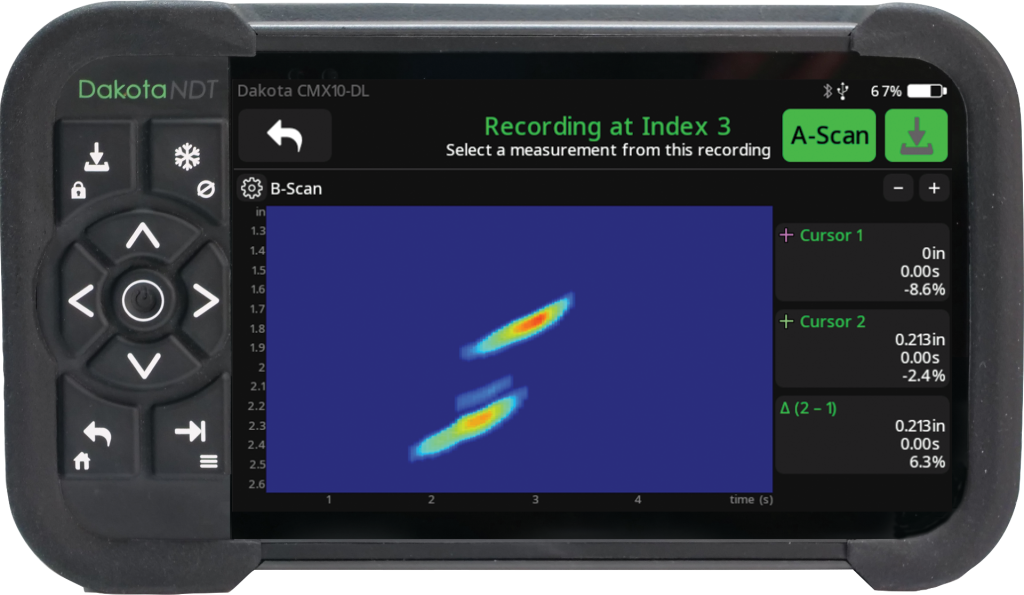
Internal Defect With point-to-point measurement
B-Scan supports additional identification of defects in a composite layer beyond that of a traditional A- Scan gauge.
Cursors for point to point measurement provide accurate depth measurement.
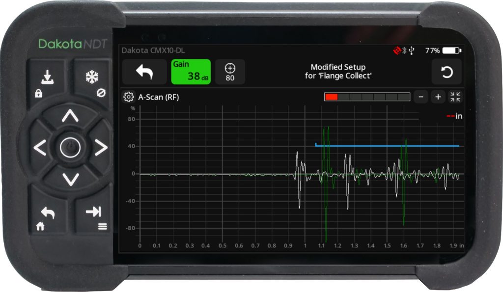
Overlay Comparison Identify differences in waveforms
The Dakota CMX10-DL ultrasonic thickness gauge can help identify differences in waveform signal patterns to indicate changes in structure or areas of concern.
Product Features of Dakota CMX10-DL (Full Wave Capture Thickness Gauge)
| Model | CMX10-DL |
|---|---|
| Screen Displayed Range | 23.3” (592mm) (steel) |
| Measurement Range | PE: 0.007” to 58.3” (0.18mm to 1480mm) (probe dependant), EE: 0.007” to 23.3” (0.18mm to 592mm) (probe dependant), EEV: 0.007” to 11.7” (0.18mm to 296mm) (probe dependant), 2nd Layer Thickness (PE2): 0.007” to 58.3” (0.18mm to 1480mm) (probe dependant), 2nd Layer Thickness ThruPaint™ (EE2): 0.007” to 23.3” (0.18mm to 592mm) (probe dependant) |
| Velocity Calibration Range | 0.0079 to 0.7874 in/μs / (200 to 20000 m/sec) |
| Transmitter Pulse | Square |
| Transmitter Pulse Voltage (peak-to-peak) | 50 - 200V (User Adjustable in 1Volt steps) |
| Pulse Rise Time | <10 ns |
| Pulse Duration | 25 to 250nS (Dependent on probe frequency) |
| Gain Control | 0-74dB in 0.1dB steps features: Time Controlled Gain, Auto80 |
| Transducer Frequency Range | 1 - 20MHz |
| Measurement Accuracy | 0.001” (±0.01mm) or ±1% of Reading (whichever is largest) *@ 5MHz 1/4” on Steel. |
| Measurement Resolution | ±0.0001” (±0.001mm) |
| Min & Max Measurement | (Steel @ 5920m/s) Minimum: 0.007” (0.18mm) Maximum: 23.3” (592mm) (Delay: 0.1” - 35” (-3mm - 888mm)) |
| Calibration Options | Zero (using the integral zero disc) , 1 - point, 2 - point , Custom Velocity, Preset Material |
| Gates | Flank, Zero-Cross, Peak |
| Number Gates | 1-3 Depending on Mode Selected |
| Filter Settings | Low Pass (10Mhz, 20Mhz, 30Mhz), High Pass (0.5Mhz, 2.5Mhz, 5Mhz) and Broadband |
| Time Corrected Gain (TCG) | Ramp, Curve (up to 16 points) |
| Pulse Repetition Frequencies (PRFs) | 2KHz |
| Back Wall Echo Suppression | ⬛ |
| V-path / dual path error correction | Automatically corrects for V-path (Dakota NDT transducers only) |
| DakMaster Software™ | ⬛ |
| DakMaster™ Mobile App | ⬛ |
| Transducer Probe Type | Dual Contact, Single Contact, Single Delay, Angular (Prove Up) |
| Auto Detect & Transducer Set Up | Feature compatible with ODU style Transducers |
| Display | 800 x 480 pixels, Colour, Touchscreen, Graphical, TFT Display |
| Display Refresh Rate | 60Hz |
| Waveform Refresh Rate | 20Hz (50ms) |
| Display & Recall Facilities | Numerical Reading, A- Scan, B- Scan and Video Recordings can be stored and retrieved in Data logs |
| A-Scan | Rectified +/-, RF, Full Wave |
| B-Scan | Timed Includes Recording and Analysis with 2 Curser Measurement |
| Differential Mode | ⬛ |
| Display Freeze | Freeze Screen and Overlay Signal on Screen |
| Expanded Gate | Expand signal displayed under gate |
| Transducer Stability Indicator | Speed 20Hz (50ms) |
| Display Colour Inversion | A- Scan Sunlight Assist |
| Brightness Adjust | Manual and automatic screen brightness level adjustment |
| Display Configurations | A-Scan, Statistics, Live Reading, Grid, Image Collect |
| Image Collect Library | Part Display Images (Multiple Formats) |
| Screen Share & Control | Remote Viewing Feature with Control |
| Data Output | USB and Bluetooth® LE Data Output |
| Log Formats | Sequential, Grid, Recording, Amplitude/Depth Colour Options |
| Screen Capture | On Gauge and Screen view function in DakMaster™ |
| Note Ability | OBSTRUCT to indicate inaccessible, with notes |
| Full Traceability Feature | Set Up Library, Transducer Library, Calibration Library |
| Data Log File Format Options | Projects, Folders, Individual Files |
Technical Specification of Dakota CMX10-DL (Full Wave Capture Thickness Gauge)
| Part Number | Description |
|---|---|
| CMX10-DL | Dakota CMX10-DL Full Wave Capture Thickness Gauge |
| Operation of Gauge Controls | Keypad Only, Touchscreen Only or Keypad & Touchscreen Combined Control |
| Gauge Dimensions | 7.1 x 4.1 x 2.0" (180 x 105 x 50mm) |
| Gauge Weight | 1.92lbs (872g) |
| Operating Temperature | 14ºF to 122ºF (-10 to 50ºC) |
| Probe Sockets Type(s) | 1/2 x Lemo-00 1x ODU Smart Port |
| Power Supply | LI-Ion - Rechargeable Smart Battery or Mains Power Supply |
| Battery Life | 9 to 15 hrs (Dependant on usage) |
| Ingress Protection (IP) | Dust tight and protected against low power water jets in any direction; equivalent to IP65 |
| Certification | Calibration Certificate |
| Warranty | 1 year limited |
| Manufacture | Made in the United Kingdom |
| Packing List | Dakota CMX10-DL Gauge, Ultrasonic Couplant; 120ml (4fl oz), Power Supply (UK, EU and US) Adapters, Rechargeable Battery, Hand Strap (x1), Extension straps (x2), Screen Protector x 1, USB Cable, Calibration Certificate, User Guide, DakMaster™ download card, Transit Case |